

How Many Amps Do 12 Volt Led Lights Draw

LEDs
Testing | Colour | Sizes & shapes | Resistor | LEDs in serial | LED data | Flashing | Displays
As well see: Lamps | Diodes
LED = Light Emitting Diode
LEDs emit lite when an electric current passes through them.
The electrical behaviour of an LED is quite dissimilar from a lamp and it must be protected from passing excessive electric current, usually this is accomplished by connecting a resistor in series with the LED. Never connect an LED directly to a bombardment or power supply.

LEDs must be connected the correct style round, the diagram may be labelled a or + for anode and grand or - for cathode (yes, it really is thou, non c, for cathode). The cathode is the short lead and in that location may be a slight flat on the body of round LEDs. If you can see within the LED the cathode is the larger electrode simply this is not an official identification method.
Soldering LEDs
LEDs can exist damaged by heat when soldering but the risk is small unless yous are very slow. No special precautions are needed for soldering most LEDs.
Rapid Electronics: LEDs
Testing an LED

Never connect an LED directly to a bombardment or power supply because the LED is probable to be destroyed past excessive electric current passing through it.
LEDs must have a resistor in series to limit the current to a safe value, for testing purposes a 1k![]() resistor is suitable for most LEDs if your supply voltage is 12V or less. Remember to connect the LED the correct way round.
resistor is suitable for most LEDs if your supply voltage is 12V or less. Remember to connect the LED the correct way round.
Please see below for an explanation of how to work out a suitable resistor value for an LED.
LED Colours
The colour of an LED is determined by its semiconductor material, non by the colouring of the 'parcel' (the plastic trunk). LEDs of all colours are available in uncoloured packages which may be diffused (milky) or articulate (often described every bit 'water clear'). The coloured packages are as well available every bit diffused (the standard type) or transparent.
Blueish and white LEDs may be more expensive than the other colours.
Bi-color LEDs
A bi-colour LED has two LEDs wired in 'inverse parallel' (i forwards, 1 backwards) combined in one package with two leads. Only one of the LEDs can be lit at ane fourth dimension and they are less useful than the tri-colour and RGB LEDs described below.
Tri-colour LEDs
The near pop type of tri-colour LED has a red and a green LED combined in i bundle with iii leads. They are chosen tri-colour because mixed red and light-green low-cal appears to be yellow and this is produced when both the red and green LEDs are on.
The diagram shows the structure of a tri-colour LED. Note the dissimilar lengths of the three leads. The centre lead (one thousand) is the mutual cathode for both LEDs, the outer leads (a1 and a2) are the anodes to the LEDs assuasive each one to be lit separately, or both together to give the third colour.
Rapid Electronics: red/green LED
RGB LEDs
RGB LEDs contain Red, Greenish and Bluish LEDs in one packet. Each internal LED can be switched on and off separately allowing a range of colours to be produced:
- Red + Green gives Xanthous
- Cherry-red + Blue gives Magenta
- Green + Bluish gives Cyan
- Red + Light-green + Blue gives White
A wider range of colours can be produced by varying the brightness of each internal LED.
Rapid Electronics: RGB LED
Sizes, Shapes and Viewing angles of LEDs
LEDs are available in a broad diverseness of sizes and shapes. The 'standard' LED has a circular cross-section of 5mm diameter and this is probably the all-time type for general use, just 3mm round LEDs are also popular.
Round cross-department LEDs are frequently used and they are very like shooting fish in a barrel to install on boxes by drilling a hole of the LED diameter, adding a spot of mucilage will help to hold the LED if necessary. LED clips (illustrated) are also available to secure LEDs in holes. Other cantankerous-section shapes include square, rectangular and triangular.
Photograph © Rapid Electronics
Likewise equally a variety of colours, sizes and shapes, LEDs also vary in their viewing angle. This tells you how much the axle of light spreads out. Standard LEDs take a viewing angle of threescore° merely others have a narrow axle of xxx° or less.
Rapid Electronics stock a particularly wide selection of LEDs and their website is a proficient guide to the extensive range available including the latest high power LEDs.
Calculating an LED resistor value
An LED must take a resistor connected in serial to limit the current through the LED, otherwise it will burn out most instantly.
The resistor value, R is given by:
R = resistor value in ohms (![]() ).
).
VS = supply voltage.
V50 = LED voltage (2V, or 4V for blue and white LEDs).
I = LED current in amps (A)

The LED current must be less than the maximum permitted for your LED. For standard 5mm diameter LEDs the maximum current is usually 20mA, so 10mA or 15mA are suitable values for many circuits. The electric current must be in amps (A) for the calculation, to convert from mA to A split the electric current in mA by k.
If the calculated value is not bachelor choose the nearest standard resistor value which is greater, and so that the current will exist a little less than you chose. In fact you lot may wish to choose a greater resistor value to reduce the current (to increase battery life for instance) but this will make the LED less bright.
For example
If the supply voltage VS = 9V, and you have a reddish LED (FiveL = 2V), requiring a current I = 20mA = 0.020A,
R = (9V - 2V) / 0.02A = 350![]() , so choose 390
, so choose 390![]() (the nearest standard value which is greater).
(the nearest standard value which is greater).
LED voltage
The LED voltage VL is determined by the color of the LED. Ruddy LEDs have the everyman voltage, yellow and light-green are a little higher. Bluish and white LEDs have the highest voltages.
For most purposes the exact value is not disquisitional and you can employ 2V for red, yellowish and light-green, or 4V for blue and white LEDs.
Working out the LED resistor formula using Ohm'southward law
Ohm'due south police force says that the resistance of the resistor, R = V/I, where:
V = voltage across the resistor (= VS - VL in this case)
I = the current through the resistor
So R = (VS - 550) / I
For more than information on the calculations please see the Ohm'southward Law page.
Connecting LEDs in serial
If you wish to have several LEDs on at the aforementioned fourth dimension it may be possible to connect them in serial. This prolongs battery life by lighting several LEDs with the aforementioned current as merely 1 LED.
All the LEDs connected in series pass the same current and so information technology is best if they are all the same type. The power supply must have sufficient voltage to provide about 2V for each LED (4V for blue and white) plus at least another 2V for the resistor. To work out a value for the resistor you must add up all the LED voltages and use this for VFifty.
Case calculations:
A carmine, a yellowish and a greenish LED in series need a supply voltage of at least iii × 2V + 2V = 8V, so a 9V bombardment would be ideal.
V50 = 2V + 2V + 2V = 6V (the three LED voltages added up).
If the supply voltage VS is 9V and the current I must exist 15mA = 0.015A,
Resistor R = (FiveS - VFifty) / I = (9 - 6) / 0.015 = 3 / 0.015 = 200![]() ,
,
so choose R = 220![]() (the nearest standard value which is greater).
(the nearest standard value which is greater).
Avoid connecting LEDs in parallel!

Connecting several LEDs in parallel with but i resistor shared betwixt them is generally a bad idea.
If the LEDs require slightly different voltages only the lowest voltage LED volition light and information technology may be destroyed by the larger electric current flowing through it. Although identical LEDs tin be successfully connected in parallel with one resistor this rarely offers whatever useful benefit because resistors are very cheap and the current used is the same as connecting the LEDs individually.
If LEDs are in parallel each 1 should accept its ain resistor.
Reading a table of technical data for LEDs
Suppliers' websites and catalogues ordinarily provide tables of technical data for components such every bit LEDs. These tables incorporate a good deal of useful information in a meaty form but they can exist difficult to sympathize if you are not familiar with the abbreviations used. These are the important backdrop for LEDs:
- Maximum forward current, IF max.
'Forward' just means with the LED continued correctly. - Typical forward voltage, VF typ.
This is 5L in the LED resistor adding, about 2V, or 4V for blue and white LEDs. - Luminous intensity
Brightness at the specified current, east.g. 32mcd @ 10mA (mcd = millicandela). - Viewing angle
60° for standard LEDs, others emit a narrower beam of nigh 30°. - Wavelength
The peak wavelength of light emitted, information technology determines the colour of the LED, e.m. red 660nm, blue 430nm (nm = nanometre).
The following 2 properties can be ignored for well-nigh circuits:
- Maximum forward voltage, VF max.
This can be ignored if you have a suitable resistor in serial. - Maximum reverse voltage, FiveR max.
This can be ignored for LEDs connected the right way round.
Flashing LEDs
Flashing LEDs expect like ordinary LEDs only they contain an IC (integrated circuit) equally well every bit the LED itself. The IC flashes the LED at a low frequency, for instance 3Hz (3 flashes per second). Flashing LEDs are designed to be continued direct to a particular supply voltage such as 5V or 12V without a series resistor. Check with the supplier to find the safe supply voltage range for a particular flashing LED. The flash frequency is fixed and so their utilise is limited and you may prefer to build your own circuit to flash an ordinary LED, for instance the Flashing LED projection which uses a 555 astable circuit.
Rapid Electronics: Flashing LEDs

LED Displays
LED displays are packages of many LEDs arranged in a pattern, the most familiar pattern being the 7-segment displays for showing numbers (digits 0-9). The pictures below illustrate some of the pop designs.
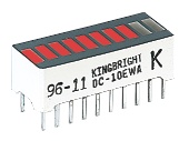
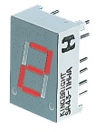


Bargraph, 7-segment, Starburst and Dot-matrix LED displays
Photographs © Rapid Electronics
Rapid Electronics: LED displays
Pin connections of LED displays
In that location are many types of LED display and a supplier'south catalogue or website should be consulted for the pin connections. The diagram on the right shows an example from Rapid Electronics. Like many 7-segment displays, this example is available in ii versions: Mutual Anode (SA) with all the LED anodes connected together and Common Cathode (SC) with all the cathodes connected together. Letters a-thou refer to the seven segments, A/C is the mutual anode or cathode as appropriate (on 2 pins). Note that some pins are non nowadays (NP) but their position is still numbered.
Besides see: Display Drivers.
Rapid Electronics have kindly allowed me to utilise their images on this website and I am very grateful for their support. They stock a wide range of LEDs, other components and tools for electronics and I am happy to recommend them as a supplier.
Books on components:
- Electronic Components, Volume 1
- Electronic Components, Volume 2
- Electronic Components, Volume 3

Source: https://electronicsclub.info/leds.htm
Posted by: bentleyswuzzin.blogspot.com
0 Response to "How Many Amps Do 12 Volt Led Lights Draw"
Post a Comment